
Items related to Solid Biomechanics
Synopsis
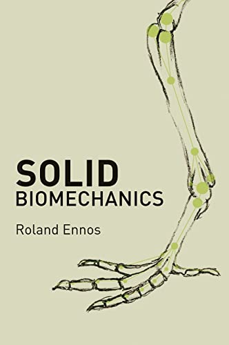
Solid Biomechanics is the first book to comprehensively review the mechanical design of organisms. With a physical approach and a minimum of mathematics, the textbook introduces readers to the world of structural mechanics and sheds light on the dazzling array of mechanical adaptations that link creatures as dissimilar as bacteria, plants, and animals. Exploring a wide range of subjects in depth, from spider silks and sharkskin to climbing plants and human food processing, this immensely accessible text demonstrates that the bodies of animals and plants are masterpieces of engineering, enabling them to survive in a hostile world.
The textbook describes how organisms construct materials from limited components, arrange materials into efficient structures that withstand different types of stresses, and interact mechanically with their environment. Looking at practical and historical aspects of the subject, the book delves into how the mechanics of organisms might be applied to other engineering scenarios and considers the ways structural biomechanics could and should develop in the future if more is to be learned about the form and function of organisms. Solid Biomechanics will be useful to all those interested in how organisms work, from biologists and engineers to physicists and students of biomechanics, bionics, and materials science.
- The first comprehensive review of the structural mechanics of organisms
- Introduces the subject using a physical approach involving minimal mathematics
- Three complementary sections: materials, structures, and mechanical interactions of organisms
- Links the dazzling array of mechanical adaptations seen in widely differing organisms
- Practical and historical approach shows how mechanical adaptations have been discovered and how readers can perform their own investigations
"synopsis" may belong to another edition of this title.
About the Author
Roland Ennos is a reader in ecology at the University of Manchester. He is the author of Trees.
From the Back Cover
"The publication of this book is nothing if not auspicious. In Solid Biomechanics, Ennos brings to bear his unusually wide experience, from early work on insect flight to extensive recent research on plants. This is a book that we very much need."--Steven Vogel, professor emeritus, Duke University
"This accessible and clear book looks at how the structure and mechanical properties of tissues and organs of living organisms relate to their function. Discussing many kinds of tissues--plant, animal, and human--Solid Biomechanics will generate broad interest in the subject."--Rod Lakes, University of Wisconsin
From the Inside Flap
"The publication of this book is nothing if not auspicious. In Solid Biomechanics, Ennos brings to bear his unusually wide experience, from early work on insect flight to extensive recent research on plants. This is a book that we very much need."--Steven Vogel, professor emeritus, Duke University
"This accessible and clear book looks at how the structure and mechanical properties of tissues and organs of living organisms relate to their function. Discussing many kinds of tissues--plant, animal, and human--Solid Biomechanics will generate broad interest in the subject."--Rod Lakes, University of Wisconsin
Excerpt. © Reprinted by permission. All rights reserved.
Solid Biomechanics
By Roland EnnosPRINCETON UNIVERSITY PRESS
Copyright © 2012 Princeton University PressAll right reserved.
ISBN: 978-0-691-13550-2
Contents
Preface.....................................................................xiAcknowledgments.............................................................xiiiCHAPTER 1 The Properties of Materials.......................................3CHAPTER 2 Biological Rubbers................................................29CHAPTER 3 Complex Polymers..................................................42CHAPTER 4 Polymer Composites................................................59CHAPTER 5 Composites Incorporating Ceramics.................................83CHAPTER 6 Tensile Structures................................................95CHAPTER 7 Hydrostatic Skeletons.............................................111CHAPTER 8 Structures in Bending.............................................123CHAPTER 9 Structures in Compression.........................................147CHAPTER 10 Structures in Torsion............................................159CHAPTER 11 Joints and Levers................................................170CHAPTER 12 Attachments......................................................183CHAPTER 13 Interactions with the Mechanical Environment.....................198CHAPTER 14 Mechanical Interactions between Organisms........................206CHAPTER 15 The Future of Structural Biomechanics............................219Glossary....................................................................223References..................................................................231Index.......................................................................247
Chapter One
The Properties of Materials
FORCES: DYNAMICS AND STATICS
We all have some intuitive idea about the mechanics of the world around us, an idea built up largely from our own experience. However, a proper scientific understanding of mechanics has taken centuries to achieve. Isaac Newton was of course the founder of the science of mechanics; he was the first to describe and understand the ways in which moving bodies behave.
Introducing the concepts of inertia and force, he showed that the behavior of moving bodies could be summed up in three laws of motion.
1) The law of inertia: An object in motion will remain in motion unless acted upon by a net force. The inertia of an object is its reluctance to change its motion.
2) The law of acceleration: The acceleration of a body is equal to the force applied to it divided by its mass, as summarized in the equation
F = ma, (1.1)
where F is the force; m, the mass; and a, the acceleration.
3) The law of reciprocal action: To every action there is an equal and opposite reaction. If one body pushes on another with a given force, the other will push back with the same force in the opposite direction.
To summarize with a simple example: if I give a push to a ball that is initially at rest (fig. 1.1a), it will accelerate in that direction at a rate proportional to the force and inversely proportional to its mass. The great step forward in Newton's scheme was that, together with the inverse square law of gravity, it showed that the force that keeps us down on earth is one and the same with the force that directs the motion of the planets.
All this is a great help in understanding dynamic situations, such as billiard balls colliding, guns firing bullets, planets circling the sun, or frogs jumping. Unfortunately it is much less useful when it comes to examining what is happening in a range of no-less-common everyday situations. What is happening when a book is lying on a desk, when a light bulb is hanging from the ceiling, or when I am trying to pull a tree over? (See fig. 1.1b.) In all of these static situations, it is clear that there is no acceleration (at least until the tree does fall over), so the table or rope must be resisting gravity and the tree must be resisting the forces I am putting on it with equal and opposite reactions. But how do objects supply that reaction, seeing as they have no force-producing muscles to do so? The answer lies within the materials themselves.
Robert Hooke (1635–1703) was the first to notice that when springs, and indeed many other structures and pieces of material, are loaded, they change shape, altering in length by an amount approximately proportional to the force applied, and that they spring back into their original shape after the load is removed (fig. 1.2a). This linear relationship between force and extension is known as Hooke's law.
What we now know is that all solids are made up of atoms. In crystalline materials, which include not only salt and diamonds but also metals, such as iron, the atoms are arranged in ordered rows and columns, joined by stiff interatomic bonds. If these sorts of materials are stretched or compressed, we are actually stretching or compressing the interatomic bonds (fig. 1.2b). They have an equilibrium length and strongly resist any such movement. In typically static situations, therefore, the applied force is not lost or dissipated or absorbed. Instead, it is opposed by the equal and opposite reaction force that results from the tendency of the material that has been deformed to return to its resting shape. No material is totally rigid; even blocks of the stiffest materials, such as metals and diamonds, deform when they are loaded. The reason that this deformation was such a hard discovery to make is that most structures are so rigid that their deflection is tiny; it is only when we use compliant structures such as springs or bend long thin beams that the deflection common to all structures is obvious.
The greater the load that is applied, the more the structure is deflected, until failure occurs; we will then have exceeded the strength of our structure. In the case of the tree (fig. 1.1b), the trunk might break, or its roots pull out of the soil and the tree accelerate sideways and fall over.
INVESTIGATING THE MECHANICAL PROPERTIES OF MATERIALS
The science of elasticity seeks to understand the mechanical behavior of structures when they are loaded. It aims to predict just how much they should deflect under given loads and exactly when they should break. This will depend upon two things. The properties of the material are clearly important—a rod made of rubber will stretch much more easily than one made of steel. However, geometry will also affect the behavior: a long, thin length of rubber will stretch much more easily than a short fat one.
To understand the behavior of materials, therefore, we need to be able separate the effects of geometry from those of the material properties. To see how this can be done, let us examine the simplest possible case: a tensile test (fig. 1.3a), in which a uniform rod of material, say a rubber band, is stretched.
The Concept of Stress
If it takes a unit force to stretch a rubber band of a given cross-sectional area a given distance, it can readily be seen that it will take twice the force to give the same stretch to two rubber bands set side by side or to a single band of twice the thickness. Resistance to stretching is therefore directly proportional to the cross-sectional area of a sample. To determine the mechanical state of the rubber, the force applied to the sample must consequently be normalized by dividing it by its cross-sectional area. Doing so gives a measurement of the force per unit area, or the intensity of the force, which is known as stress and which is usually represented by the symbol σ, so that
σ = P/A, (1.2)
where P is the applied load and A the cross-sectional area of the sample. Stress is expressed in SI units of newtons per square meter (N m-2) or pascals (Pa). Unfortunately, this unit is inconveniently small, so most stresses are given in kPa (N m-2 × 10³)), MPa (N m-2 × 10⁶), or even Gpa (N m-2 × 10⁹).
The Concept of Strain
If it takes a unit force to stretch a rubber band of a given length by a given distance, the same force applied to two rubber bands joined end to end or to a single band of twice the length will result in twice the stretch. Resistance to stretching is therefore inversely proportional to the length of a sample. To determine the change in shape of the rubber as a material in general, and not just of this sample, the deflection of the sample must consequently be normalized by dividing by its original length. This gives a measure of how much the material has stretched relative to its original length, which is known as strain and which is usually represented by the symbol, , so that
ε = dL/L, (1.3)
where dL is the change in length and L the original length of the sample. Strain has no units because it is calculated by dividing one length by another.
It is perhaps unfortunate that engineers have chosen to give the everyday words stress and strain such precise definitions in mechanics, since doing so can confuse communications between engineers and lay people who are used to the vaguer uses of these words. As we shall see, similar confusion can also be a problem with the terms used to describe the mechanical properties of materials.
DETERMINING MATERIAL PROPERTIES
Many material properties can be determined from the results of a tensile test once the graph of force against displacement has been converted with equations 1.2 and 1.3 into one of stress versus strain. Figure 1.3b shows the stress-strain curve for a typical tough material, such as a metal. Like many, but by no means all, materials, this one obeys Hooke's law, showing linear elastic behavior: the stress initially increases rapidly in direct proportion to the strain. Then the material reaches a yield point, after which the stress increases far more slowly, until finally failure occurs and the material breaks.
The first important property that can be derived from the graphs is the stiffness of the material, also known as its Young's modulus, which is represented by the symbol E. Stiffness is equal to the initial slope of the stress-strain curve and so is given mathematically by the expression
E = dσ/dε (1.4)
or by the original force-displacement curve
E = LdP/AdL. (1.5)
Stiff materials therefore have a high Young's modulus. Compliance is the inverse of stiffness, so compliant materials have a low Young's modulus. In many materials, the slope of the curve changes as the material is stretched. For such materials one can distinguish between the initial stiffness and the tangent stiffness, which is the slope at higher strains.
The second important property that can be derived is the strength, or breaking stress, of the material; this is simply the maximum value of stress, max, along the y-axis. Breaking stress can alternatively be calculated from the original force-displacement curve using the formula
σmax = Pmax/A. (1.6)
Strong materials have a high breaking stress, whereas weak ones have a low breaking stress. The yield stress, σyield, can also be read off the graph, being the stress at which it stops obeying Hooke's law and becomes more compliant; this is the point at which the slope of the graph falls.
A third useful property of a material is its extensibility, or breaking strain, εmax, which is simply the maximum value of strain along the x-axis. Breaking strain can alternatively be calculated from the original force-displacement curve using the formula
εmax = (Lmax - L)/L. (1.7)
The yield strain can also be determined from this curve, being the strain at which the slope of the graph falls.
A further material property that can be derived by examining the shape of the stress-strain curve is its susceptibility or resistance to breakage. A brittle material, such as glass, will not have a yield region but will break at the end of the straight portion (fig. 1.4), whereas a tough material, such as a metal, will continue taking on load at strains well above yield before finally breaking.
LOADING, UNLOADING, AND ENERGY STORAGE
A final useful aspect of stress-strain graphs is that the area under the curve equals the energy, We, that is needed to stretch a unit volume of the material to a given strain. This factor is given in units of joules per cubic meter (J m-3, which is dimensionally the same as N m-2). Under the linear part of the stress-strain curve, this energy equals half the stress times the strain, so
We = σε/2.
But strain equals stress divided by stiffness, so
We = σ(σ/E)/2 = σ2/2E. (1.8) The elastic storage capability, Wc, of a material is the amount of energy under the curve up to the point at which yield occurs and is given by the equation
We = σ2yield/2E. (1.9)
The amount of energy an elastic material can store, therefore, increases with its yield stress but decreases with its stiffness, because stiffer materials do not stretch as far for a given stress. So the materials that store most energy are ones that are strong but compliant.
In a perfectly elastic material, all of this energy would be stored in the material and could be recovered if it were allowed to return to its original length. However, no materials are perfectly elastic; the percentage of energy released by a material, known as its resilience, is never 100% and falls dramatically in tough materials after yield, since yield usually involves irreversible damage to the sample. The resilience of a material can be readily measured using a modified tensile test in which the sample is stretched to a point before yield occurs and then allowed to return to its rest length. The unloading curve will always be below the loading curve. The resilience is the percentage of the area under the unloading curve divided by the area under the loading curve; the percentage of energy that is lost is known as the hysteresis and is the remainder of 100% minus the resilience.
Loading/unloading tests can be used to differentiate between different sorts of materials. In a perfectly elastic material (fig. 1.5a), the unloading curve follows the loading curve exactly, there is no hysteresis, and the material returns to its original shape after the test. In a perfectly plastic material, on the other hand (fig. 1.5b), the material will be permanently deformed by the load, and all the energy put into it will be dissipated. Tough materials often show elastic-plastic behavior (fig. 1.5c), acting elastically before and plastically after yield, in which case the sample will return only part of the way to its original shape and some energy will be dissipated in deforming it permanently. Finally, even before yield, materials often show viscoelastic behavior (fig. 1.5d), in which energy is lost as they deform, just as it does in liquids, due to internal friction. The amount of energy lost and hence the shape of the loading/unloading curve will vary with the speed at which the test is carried out, as we shall see in Chapter 3, but unlike with elastic-plastic behavior, the material will eventually return to its original shape.
THE EFFECT OF DIRECTION
Many engineering materials, such as metals, plastics, and concrete, are essentially homogenous and have the same material properties in all directions. These are said to be isotropic. Many other materials, on the other hand, particularly those with a complex internal structure (including many if not most biological materials), have very different mechanical properties in different directions. These materials are said to be anisotropic, and to fully characterize them, materials tests must be carried out in all three planes.
CHANGES IN SHAPE DURING AXIAL LOADING
When a typical material sample is put into axial loading, that is, being stretched or compressed, it does not only get longer or shorter; it also gets narrower or thicker, necking or bulging under the load (fig. 1.6). As a consequence, in a tensile test the load will be spread over a smaller area, and so the actual stress in the sample will be greater than the stress given by dividing the load by the original area. The shape of the sample will also be elongated by more than the value given by dividing the change in length by the original area. In other words, both the stress and the strain will be underestimated. In most engineering materials, which deform by no more than 0.1–1% of their original length before they break, this is not a great problem. Engineers usually do not bother to try and calculate the true stress and true strain in their samples. Instead they use the convention of ignoring the change in shape and instead calculating what are known as engineering stress and engineering strain from the original dimensions of the sample. With such small changes in shape, the error would in any case be small.
For many biological materials, on the other hand, strains can be far greater, reaching values up to 10, meaning stretches of 1000%! In these cases the differences between true stress and strain and engineering stress and strain can be very great indeed. However, because it is difficult to measure changes in shape during the course of materials tests, even biologists usually use engineering stress and strain, although, as we shall see, measuring the actual changes in shape can also provide other information about the material.
(Continues...)
Excerpted from Solid Biomechanicsby Roland Ennos Copyright © 2012 by Princeton University Press. Excerpted by permission of PRINCETON UNIVERSITY PRESS. All rights reserved. No part of this excerpt may be reproduced or reprinted without permission in writing from the publisher.
Excerpts are provided by Dial-A-Book Inc. solely for the personal use of visitors to this web site.
"About this title" may belong to another edition of this title.
Search results for Solid Biomechanics

Stock Image
Solid Biomechanics
Published by
Princeton University Press, 2011
ISBN 10: 0691135509
ISBN 13: 9780691135502
New
Hardcover
Seller: PlumCircle, West Mifflin, PA, U.S.A.
Seller rating 5 out of 5 stars

hardcover. Condition: New. New item in gift quality condition. 99% of orders arrive in 4-10 days. Discounted shipping on multiple books. Seller Inventory # mon0001379705
Stock Image
Solid Biomechanics
Published by
Princeton University Press, 2011
ISBN 10: 0691135509
ISBN 13: 9780691135502
Used
Hardcover
Seller: Better World Books, Mishawaka, IN, U.S.A.
Seller rating 5 out of 5 stars
Condition: Very Good. Pages intact with possible writing/highlighting. Binding strong with minor wear. Dust jackets/supplements may not be included. Stock photo provided. Product includes identifying sticker. Better World Books: Buy Books. Do Good. Seller Inventory # 57615840-6
Stock Image
Solid Biomechanics
Published by
Princeton University Press, 2011
ISBN 10: 0691135509
ISBN 13: 9780691135502
Used
Paperback
Seller: WorldofBooks, Goring-By-Sea, WS, United Kingdom
Seller rating 5 out of 5 stars
Paperback. Condition: Very Good. The book has been read, but is in excellent condition. Pages are intact and not marred by notes or highlighting. The spine remains undamaged. Seller Inventory # GOR011093054
Buy Used
US$ 9.42
US$ 7.40 shipping
Ships from United Kingdom to U.S.A.
Ships from United Kingdom to U.S.A.
Quantity: 1 available
Stock Image
Solid Biomechanics
Published by
Princeton University Press, 2011
ISBN 10: 0691135509
ISBN 13: 9780691135502
New
Hardcover
Seller: Mesilla Internet, Las Cruces, NM, U.S.A.
Seller rating 2 out of 5 stars

Condition: New. Seller Inventory # 1244C-2-6-23-1213
Stock Image
Solid Biomechanics
Published by
Princeton University Press, 2011
ISBN 10: 0691135509
ISBN 13: 9780691135502
New
Hardcover
Seller: Mesilla Internet, Las Cruces, NM, U.S.A.
Seller rating 2 out of 5 stars
Condition: New. Seller Inventory # 1244C-2-6-23-1211
Stock Image
Solid Biomechanics
Published by
Princeton University Press, 2011
ISBN 10: 0691135509
ISBN 13: 9780691135502
Used
Hardcover
Seller: World of Books (was SecondSale), Montgomery, IL, U.S.A.
Seller rating 5 out of 5 stars
Hardback. Condition: Very Good. Reviews the mechanical design of organisms. With a physical approach and a minimum of mathematics, this book introduces readers to the world of structural mechanics and sheds light on an array of mechanical adaptations that link creatures as dissimilar as bacteria, plants, and animals. Seller Inventory # 00107146726
Stock Image
Solid Biomechanics
Published by
Princeton University Press, 2011
ISBN 10: 0691135509
ISBN 13: 9780691135502
Used
Hardcover
Seller: World of Books (was SecondSale), Montgomery, IL, U.S.A.
Seller rating 5 out of 5 stars
Hardback. Condition: Good. Reviews the mechanical design of organisms. With a physical approach and a minimum of mathematics, this book introduces readers to the world of structural mechanics and sheds light on an array of mechanical adaptations that link creatures as dissimilar as bacteria, plants, and animals. Seller Inventory # 00099434745
Stock Image
Solid Biomechanics
Published by
Princeton University Press, 2011
ISBN 10: 0691135509
ISBN 13: 9780691135502
Used
Hardcover
Seller: World of Books Inc, Montgomery, IL, U.S.A.
Seller rating 4 out of 5 stars

Hardback. Condition: Good. Reviews the mechanical design of organisms. With a physical approach and a minimum of mathematics, this book introduces readers to the world of structural mechanics and sheds light on an array of mechanical adaptations that link creatures as dissimilar as bacteria, plants, and animals. Seller Inventory # CIN0691135509G
Stock Image
Solid Biomechanics
Published by
Princeton University Press, 2011
ISBN 10: 0691135509
ISBN 13: 9780691135502
Used
Hardcover
Seller: World of Books Inc, Montgomery, IL, U.S.A.
Seller rating 4 out of 5 stars
Hardback. Condition: Very Good. Reviews the mechanical design of organisms. With a physical approach and a minimum of mathematics, this book introduces readers to the world of structural mechanics and sheds light on an array of mechanical adaptations that link creatures as dissimilar as bacteria, plants, and animals. Seller Inventory # CIN0691135509VG
Stock Image
Solid Biomechanics
Published by
Princeton University Press, Princeton NJ, 2012
ISBN 10: 0691135509
ISBN 13: 9780691135502
Used
Hardcover
Seller: Chequamegon Books, Washburn, WI, U.S.A.
Seller rating 5 out of 5 stars
Hardcover. Condition: As New with no dust jacket. 250 pages; 7 1/8 x 10 1/4". Seller Inventory # 102401